The PLR-GPTR Gas-Solid Phase Photothermal Reactor is designed for photothermal synergistic catalytic reactions.
PLR-GPTR Gas-Solid Phase Photothermal Reactor employs a flat reaction vessel and is used for gas-solid phase photocatalytic and photothermal experiments. It allows real-time monitoring of pressure and catalyst bed temperature during reactions using pressure and temperature sensors.
The PLR-GPTR Gas-Solid Phase Photothermal Reactor comes in several models including PLR-GPTR50T, PLR-GPTR100, PLR-GPTR200T, etc. The numeric suffix represents the effective volume of the reaction vessel, for example, "50" represents a reaction vessel volume of 50 mL, and "T" indicates the presence of a built-in heating function in the reaction vessel.
一、PLR-GPTR Gas-Solid Phase Photothermal Reactor Structure and Parameters

Figure 1. Physical Image of the PLR-GPTR Gas-Solid Phase Photothermal Reactor
Technical Parameters:
1. Operating Temperature: Room temperature to 300°C, customizable to room temperature to 450°C;
2. Temperature Detection Accuracy: ±0.1°C;
3. Maximum Pressure: Atmospheric pressure 0~0.15 MPa, customizable up to 0.3 MPa;
4. Reactor Volume: 50 mL;
5. Optical Window Material: Imported quartz glass with light transmittance of 97%;
6. Optical Window Diameter: 47.5 mm.
二、PLR-GPTR Gas-Solid Phase Photothermal Reactor Installation and Use
Before installation, prepare the tools shown in Figure 2, including needle-nose pliers and a 4 mm Allen wrench, where "4 mm" indicates the specification of the Allen wrench.
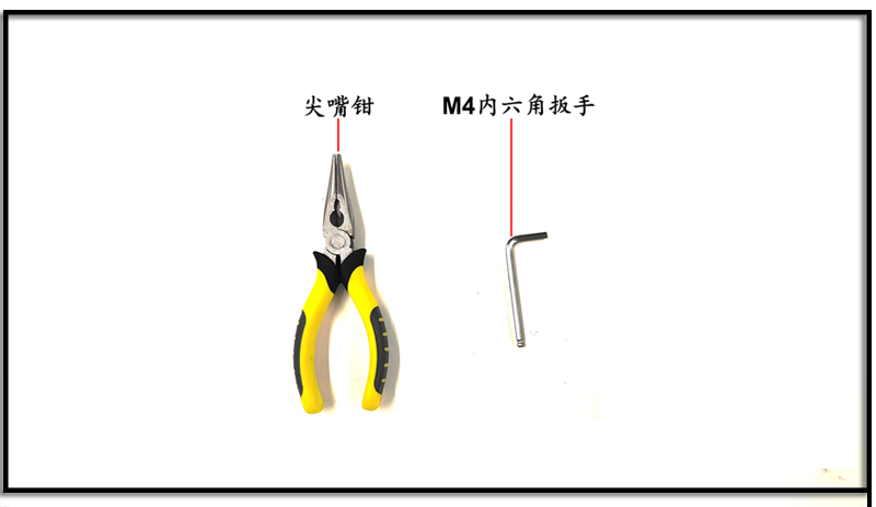
Figure 2. Tool Preparation
1. Installing the Temperature Sensor
Loosen the fixed nut at the temperature sensor location on the reaction vessel using needle-nose pliers. As shown in Figure 3, sequentially insert the O-ring, washer, and fixed nut into the temperature sensor, then insert the temperature sensor into the reaction vessel and tighten the fixed nut.
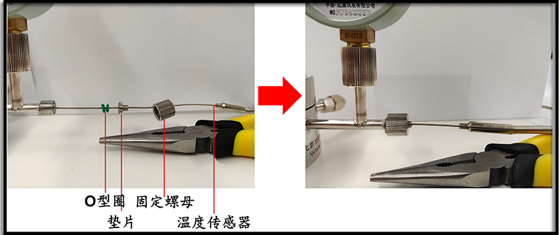
Figure 3. Temperature Sensor Installation for PLR-GPTR50 Gas-Solid Phase Photothermal Reactor
2. Setting Up the Temperature Controller
① Insert the power cord plug of the temperature controller, and the PV display will show "EEEE";
② Press "SET" on the temperature controller, and PV will display "PASS". Use the ">" button to move the cursor position, and adjust the value using the "+/-" buttons until the SV position displays "0089";
③ Press "SET" again, and PV will display "inty," and SV will display "outy";
④ After pressing "SET" again, PV will display "inty." Adjust the SV value using the "+/-" buttons until the SV position displays "K";
⑤ Unplug and then plug in the temperature controller plug again to complete the setup, as shown in Figure 4.
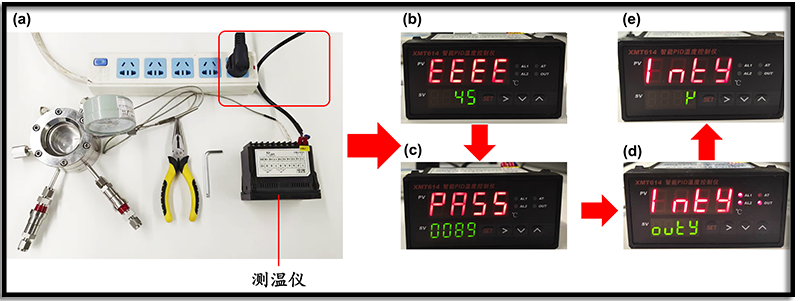
Figure 4. Temperature Controller Setup Flowchart
3. Installing the Reaction Vessel
① Use a 4 mm Allen wrench to loosen the 6 screws on the reaction vessel top cover and remove the top cover;
② Take out the two sample trays shipped together with the reaction vessel from the product packaging. Place the shallower sample tray inverted as a support tray into the reaction vessel first, and place the deeper one as the catalyst placement sample tray. After filling the sample tray with the catalyst used for the experiment, insert it into the reaction vessel. Insert the temperature sensor probe between the two sample trays and tighten the temperature sensor's fixed nut;
③ Install the O-ring for the reaction vessel top cover, cover the reaction vessel top, first align and tighten the two screws, such as 1-4 alignment, and then sequentially align and tighten the remaining screws two by two, trying to ensure that the rotation of each screw is consistent, as shown in Figure 5.
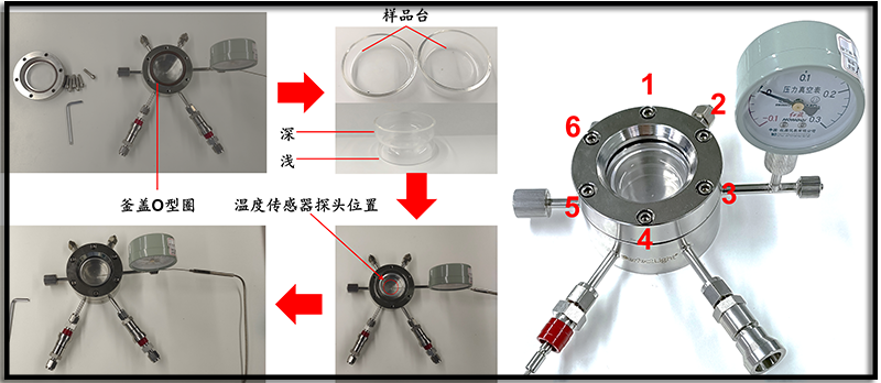
Figure 5. Assembly Process of PLR-GPTR50 Gas-Solid Phase Photothermal Reactor Reaction Vessel
4. Connecting the Gas Line
① Connect the gas line between the gas cylinder pressure reducing valve and the flow meter. You can choose an electromagnetic flow meter or a rotor flow meter for the flow meter;
If the reaction gas is a mixture, it can be used in conjunction with the PLD-DGCS05 Multi-Component Dynamic Gas Blending Instrument.
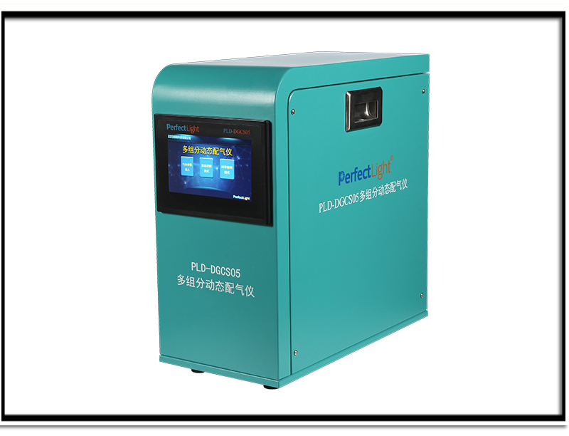
Figure 6. PLD-DGCS05 Multi-Component Dynamic Gas Blending Instrument
② Connect the gas line between the quick-connect inlet of the reaction vessel and the flow meter;
③ Connect the gas line between the quick-connect outlet of the reaction vessel and the detection instrument;
④ Connect the quick-connect inlets and outlets of the reaction vessel to the reaction vessel through push-lock connection, as shown in Figure 7.
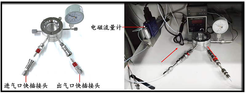
Figure 7. PLR-GPTR50 Gas-Solid Phase Photothermal Reactor Gas Line Connection Site Photo
The gas line quick-connect interface is connected to the reaction vessel inlet and outlet through a press-locking method, which allows for rapid gas on/off operations.
You can choose between a rotor flow meter or an electromagnetic flow meter.
5. Procedure for Flow Phase Reaction and Sealed Phase Reaction
① Open the reaction gas cylinder pressure reducing valve, set the pressure to 0.1 MPa, and adjust the inlet air flow rate according to experimental requirements;
② To purge the air inside the reaction vessel, perform the necessary purging operation. Calculate the purging time based on the inlet air flow rate and purging gas volume, and purge with the reaction gas for a certain period of time;

③ Flow phase reaction experiments can turn on the light source switch and start the experiment;
For sealed phase reaction experiments, adjust the reaction vessel according to the reaction pressure;
At atmospheric pressure: Quickly disconnect the inlet and outlet quick-connect interfaces;
Positive pressure experiments: Quickly disconnect the outlet quick-connect interface, adjust the gas cylinder pressure reducing valve to reach the desired pressure inside the reaction vessel, and then quickly disconnect the inlet quick-connect interface;
If heating is required, place the reaction vessel on the heating magnetic stirrer as shown in Figure 8, set the experimental temperature, and when the temperature displayed on the temperature controller reaches the required reaction temperature, turn on the xenon lamp light source switch to start the reaction.
④ After the experiment, close the gas source valve, and disassemble it after the reaction vessel temperature has cooled to room temperature.
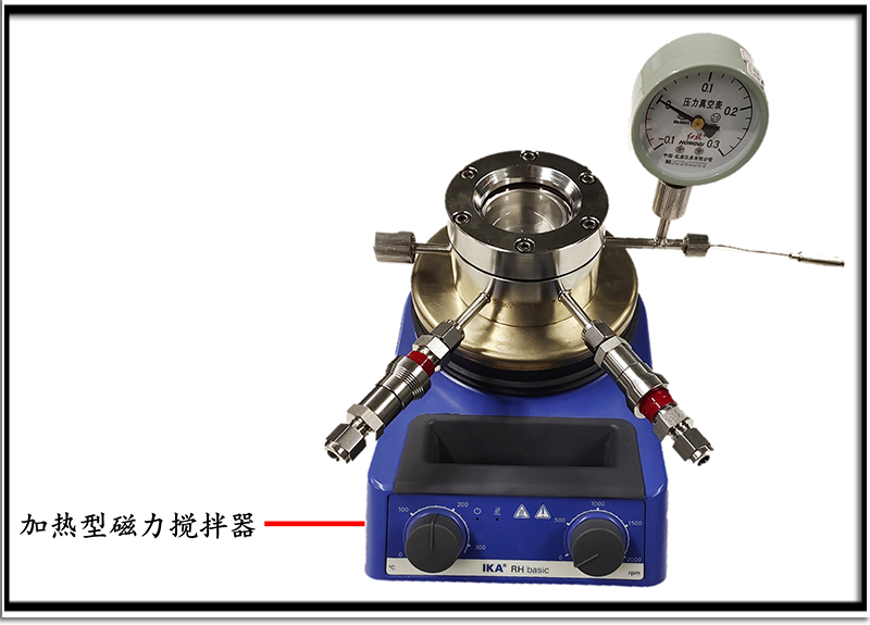
Figure 8. Heating Operation of PLR-GPTR50 Gas-Solid Phase Photothermal Reactor
四、Precautions:
1. When installing the reaction vessel top cover, make sure to tighten the screws at the alignment positions, so that the six fixed screws are evenly stressed diagonally, and do not tighten one side, which may cause the reaction vessel top cover to deform, leak gas, or break the optical window;
2. Do not exceed the maximum temperature limit;
3. Do not exceed the maximum pressure limit;
4. When opening the gas cylinder, it is recommended to start from 0.1 MPa to prevent dangerous pressure buildup;
5. When loading the catalyst, try to place the temperature sensor probe tip as close to the catalyst as possible to ensure the accuracy of temperature control;
6. After the experiment, wait for the reaction vessel to cool down and depressurize before disassembling it.