Original content is not easy; if you wish to republish this article, please contact the staff and include the source information in the republished article, otherwise legal action may be taken!
Apparent Quantum Yield (AQY) refers to the ratio of the number of electrons involved in a specific wavelength condition to the total incident photons in the system[1]. In photocatalytic reaction systems, AQY is one of the important indicators for measuring photocatalytic reaction activity.
In the photocatalytic water splitting reaction to produce hydrogen, the formula for calculating the apparent quantum yield of the product H₂ is as follows[2]:

v: Reaction rate (mol·s-1);
I: Light power density (W·m-2);
A: Incident light area (m2); λ: Incident light wavelength (nm).
For more details, please refer to the "Quantum Yield (AQY) Calculation Tutorial, Worth Having!"
To meet the experimental requirements for measuring the apparent quantum yield in photocatalytic water splitting reactions, Perfectlight Technology has introduced the PLR-QY1000 Photocatalytic Reaction Quantum Yield Measurement System, as shown in Figure 1.
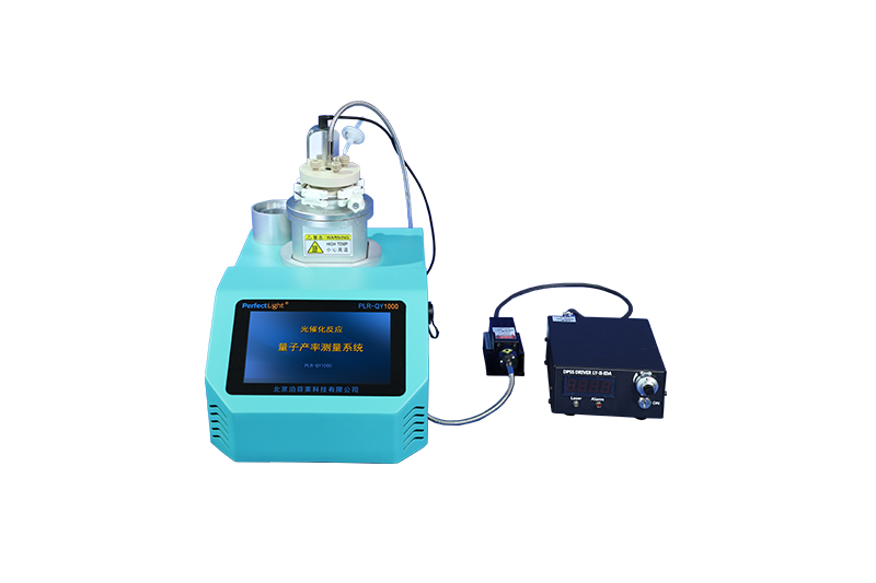
Figure 1. PLR-QY1000 Photocatalytic Reaction Quantum Yield Measurement System
PLR-QY1000 Photocatalytic Reaction Quantum Yield Measurement System uses a monochromatic laser light source for the reaction, and the spherical blackbody reactor effectively ensures that all photons are directed into the reaction system.
PLR-QY1000 Photocatalytic Reaction Quantum Yield Measurement System has built-in temperature and pressure control modules, making it convenient to study the quantum yield of photocatalysis under different temperature and pressure conditions.
PLR-QY1000 Photocatalytic Reaction Quantum Yield Measurement System uses high-precision sensors to rapidly detect H₂ molecules, ensuring measurement accuracy while monitoring the quantum yield of photocatalysts in real-time during the reaction.
PLR-QY1000 Photocatalytic Reaction Quantum Yield Measurement System has a built-in data processing module, and the quantum yield, gas production rate, total gas production, and photon number can be read directly through the system interface, allowing for direct measurement of photocatalytic quantum yield.
I. Technical Specifications of PLR-QY1000 Photocatalytic Reaction Quantum Yield Measurement System
1. Replacement Gas: N₂;
2. Reaction Pressure: 20 ~ 130 kPa, adjustable;
3. Reaction Temperature: 5 ~ 60°C;
4. Laser Light Source: Standard 405 nm laser generator, other wavelengths optional;
5. Reactor Volume: 150 mL, refer to factory calibration values for specifics.
II. Using the PLR-QY1000 Photocatalytic Reaction Quantum Yield Measurement System
1. Components
The PLR-QY1000 Photocatalytic Reaction Quantum Yield Measurement System is mainly composed of the system host, reaction bottle, reaction bottle cap, and related accessories, as shown in Figure 2.
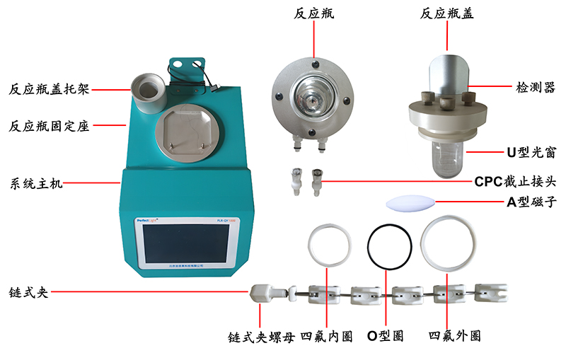
Figure 2. Components of the PLR-QY1000 Photocatalytic Reaction Quantum Yield Measurement System
2. Assembling the Reaction Bottle
2.1 Ensure that the inside of the reaction bottle and the U-shaped window are clean before use;
2.2 Fill the glass container with powdered photocatalyst and sacrificial agent solution, then disperse it evenly using an ultrasonic machine to form a suspension;
2.3 Pour the suspension into the reaction bottle, then slowly place the A-type magnet into the reaction bottle;
2.4 Place the PTFE inner ring on the mouth of the reaction bottle, then sequentially assemble the O-ring and PTFE outer ring as shown in Figure 3(a), and use the chain clamp to secure the reaction bottle cap to the reaction bottle.
Note: Do not over-tighten the chain clamp to avoid breaking the reaction bottle.
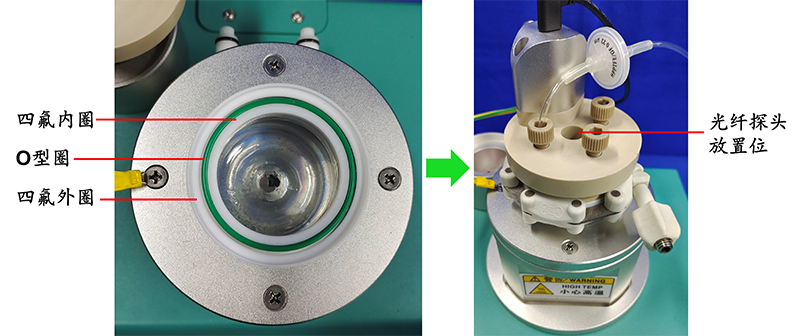
Figure 3. Assembly Diagram of the PLR-QY1000 Photocatalytic Reaction Quantum Yield Measurement System Reaction Bottle
3. Powering On and Operating
3.1 Adjust the pressure-reducing valve of the N₂ cylinder connected to the PLR-QY1000 Photocatalytic Reaction Quantum Yield Measurement System to output pressure at 0.42 MPa;
3.2 Turn on the power switch on the back panel of the PLR-QY1000 Photocatalytic Reaction Quantum Yield Measurement System host, tap the screen anywhere, and the system will perform a self-check operation automatically;
3.3 After the self-check is complete, a dialog box saying "Self-check completed, tap the screen to continue" will pop up. Tap the screen again to enter the system operating interface.
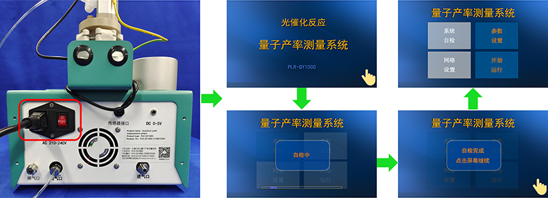
Figure 4. Rear Panel and Startup Interface of the PLR-QY1000 Photocatalytic Reaction Quantum Yield Measurement System Host
4. Assembling and Calibrating the Laser Light Source
4.1 Place the laser light source and the optical power meter as shown in Figure 5;
4.2 Position the laser light source emission port 1 cm in front of the optical power meter probe and measure the optical power of the laser light source;
4.3 Turn on the power switch on the front panel of the laser light source and turn the switch to "ON";
4.4 Adjust the current adjustment knob of the laser light source until the optical power meter displays the required optical power value for the experiment. Note: The value displayed on the optical power meter is optical power in watts (W). Pay attention to converting it to optical power density and perform the unit conversion when necessary!;
4.5 After the measurement is complete, turn the switch on the front panel of the laser light source to "OFF" and turn off the power switch. For detailed optical power measurements, refer to "PL-MW2000 High-Power Optical Power Meter Usage Guide".

Figure 5. Diagram of Laser Light Source Optical Power Measurement
5. Setting Parameters
5.1 Click on the parameter setting in the operating interface of the PLR-QY1000 Photocatalytic Reaction Quantum Yield Measurement System as shown in Figure 6 to enter the setting interface. In the dialog box, enter the following parameters as required by the experiment:
Light source power: Measured value of light power in section 4.4, unit: mW;
Light source wavelength: Wavelength of the laser light source used in the experiment;
Reaction temperature: Temperature set in the low-temperature constant temperature bath;
Reaction pressure: Set the reaction pressure based on experimental conditions, in the range of 20~130 kPa. The system will adjust the pressure according to the set pressure;
Solution volume: Volume of the suspension in section 2.3;
Atmospheric pressure: Local atmospheric pressure in the laboratory, no need to set;
Sampling interval: Interval time for recording experimental results, can be set from 1 to 30 minutes;
Number of samples: Number of data points to be recorded in the current experiment, can be set from 1 to 256;
5.2 After setting is complete, click the save button, and the interface will return to the system operation interface.

Figure 6. System operation interface and setting interface of PLR-QY1000 photocatalytic reaction quantum yield measurement system
6. Gas calibration
6.1 Prepare a bag of high-purity hydrogen gas and a sample needle, as shown in Figure 7;
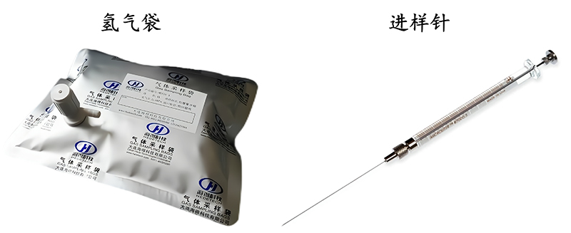
Figure 7. Hydrogen gas bag and sample needle
6.2 Click the parameter setting button in the system operation interface as shown in Figure 8 to enter the setting interface;
6.3 Click "Calibrate," a dialog box will pop up asking if you want to calibrate. Click "Confirm." The PLR-QY1000 photocatalytic reaction quantum yield measurement system will automatically perform gas replacement. After replacement, the system will enter the calibration countdown interface;
6.4 After 20 minutes of replacement, the system will automatically display a prompt dialog. Follow the prompts to inject the required volume of hydrogen gas from the standard sample port, then click "Confirm" to complete the calibration;
6.5 After calibration, the system will return to the setting interface. Click "Save" again, and the interface will return to the system operation interface.
Note: The system's calibration process is guided and can be followed step by step according to the prompts in each dialog box.
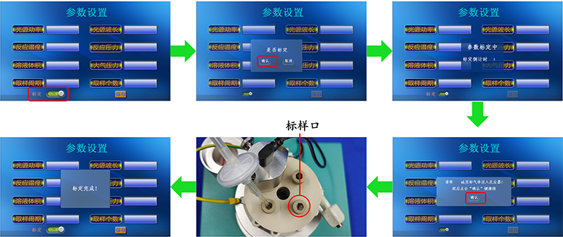
Figure 8. Calibration process of PLR-QY1000 photocatalytic reaction quantum yield measurement system
7. Preheat the system
7.1 Click "Start" on the PLR-QY1000 photocatalytic reaction quantum yield measurement system's operation interface to enter the running interface;
7.2 Click the "Settings" button on the running interface, as shown in Figure 9. Set the stirring rate in the running interface according to the experimental requirements, with a stirring rate range of 250~1250 rpm;

Figure 9. Running interface of PLR-QY1000 photocatalytic reaction quantum yield measurement system
7.3 Insert the system's provided USB drive into the side panel of the PLR-QY1000 photocatalytic reaction quantum yield measurement system, as shown in Figure 10;
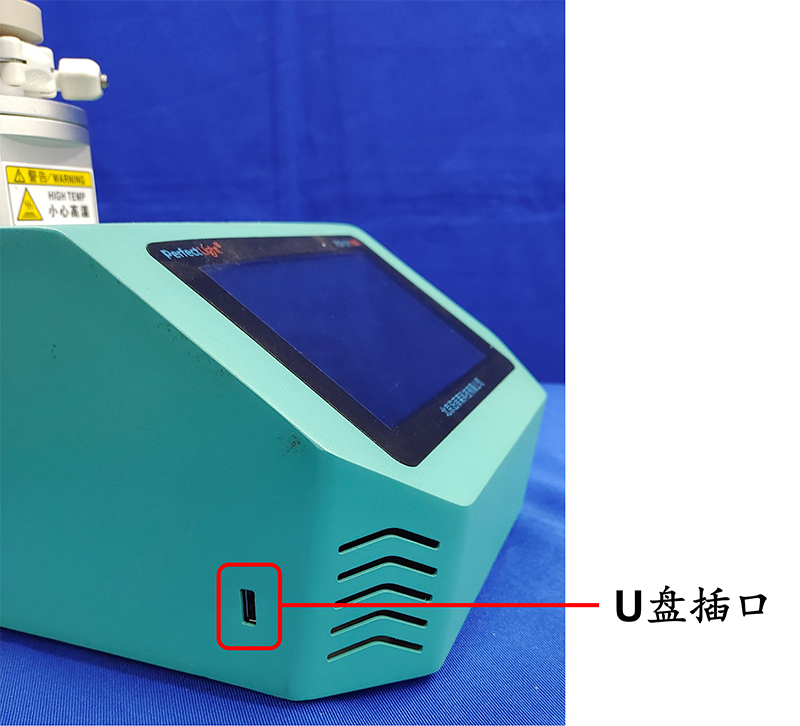
Figure 10. Side panel of PLR-QY1000 photocatalytic reaction quantum yield measurement system
7.4 Click "Start Gas Replacement" in the running interface, and a dialog box for confirmation will pop up. Click "Confirm." The system will automatically enter the gas replacement phase, where the PLR-QY1000 photocatalytic reaction quantum yield measurement system's built-in vacuum pump and gas source will perform vacuuming and gas filling operations on the reaction bottle;
7.5 After 6 gas replacements, a dialog box indicating "Gas Replacement Complete" will pop up as shown in Figure 11. The system will then automatically enter the preheating interface;
7.6 The preheating time depends on the status of the system's detector and is generally around 10~20 minutes.
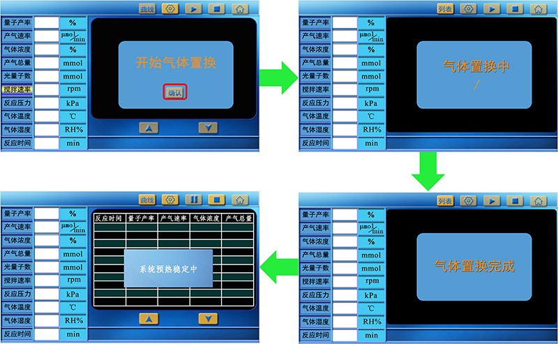
Figure 11. Gas replacement and preheating process of PLR-QY1000 photocatalytic reaction quantum yield measurement system
8. Preheat the laser light source. Turn the switch on the back panel of the laser light source to "ON" and preheat the laser light source for 15 minutes.
9. Start the experiment
9.1 After preheating the system and the laser light source, place the laser light source probe into the U-shaped window and click the ► button on the running interface, as shown in Figure 11, to start the experiment;
9.2 Once the experiment starts, the numerical values of "quantum yield, gas generation rate, gas concentration," and "total gas generation" on the screen will gradually increase from 0 and then stabilize. The stabilization time varies depending on the reaction system, generally around 45 minutes.

Figure 12. Running interface of PLR-QY1000 photocatalytic reaction quantum yield measurement system
10. End the experiment
10.1 When you need to end the experiment, click the ■ button to stop the experiment on the running interface;
10.2 Remove the laser light source probe, turn the switch on the back panel of the laser light source to "OFF," and turn off the laser light source's power switch;
10.3 Click the button on the running interface to return to the system operation interface. Click "Start" again to enter the running interface;
10.4 Click "Previous Data" to enter the historical data page. Click "Download" to download the experimental data to the USB drive. The experimental data is stored in .csv format and includes "quantum yield, gas generation rate, gas concentration," and "total gas generation" results at different time points.

Figure 13. Data download interface of PLR-QY1000 photocatalytic reaction quantum yield measurement system
10.5 After the experiment is complete, use a 12mm wrench to loosen the pressure relief nut at the "outlet" on the back panel of the system. After removing the reaction bottle cap, tighten it with the 12mm wrench;
10.6 Clean the U-shaped window and place it in the holder inside the reaction bottle.
Three, Precautions for using the PLR-QY1000 photocatalytic reaction quantum yield measurement system:
1. The gas used must be nitrogen (N₂), and the outlet pressure must be between 0.4~0.45 MPa, as other pressures can affect system self-check;
2. Keep the reaction bottle cap, O-ring, and reaction bottle mouth clean to ensure system airtightness;
3. If there is a significant change in system pressure during the preheating phase, please pay attention to airtightness issues. This may be caused by the following: ① Chain clamp on the reaction bottle cap is too tight; ② Impurities may be present on the reaction bottle cap, O-ring, and reaction bottle mouth; ③ The nut at the "outlet" on the back panel may have loosened.
[1]Wang Zheng, Li Can, Domen Kazunari*, Recent developments in heterogeneous photocatalysts for solar-driven overall water splitting[J]. Chemical. Society. Reviews, 2019, 48, 2109.
[2]Lin Huiwen, Chang Kun*, Ye Jinhua* et. al., Ultrafine nano 1T-MoS2 monolayers with NiOx as dual co-catalysts over TiO2 photoharvester for efficient photocatalytic hydrogen evolution[J]. Applied Catalysis B: Environmental, 2020, 279, 119387.