Original content is not easy. If you wish to republish this article, please contact the staff and provide proper source attribution in the republished article, or else legal action may be taken!
The PLD-DGCS05 Multi-Component Dynamic Gas Mixing System employs the mass flow rate mixing method and can be used for mixing and diluting 3 gases to obtain the desired mixed gas, expandable up to a maximum of 8 channels.
The PLD-DGCS05 Multi-Component Dynamic Gas Mixing System has two modes: Simple Control and Time Control. It can dynamically configure different concentrations of uniform multi-component mixed gases in real-time. It also features dual gas outlets. In Time Control mode, the gas composition can be switched within seconds.
PLD-DGCS05 Multi-Component Dynamic Gas Mixing System can be used in conjunction with PLR-GSPR Atmospheric Gas-Solid Phase Photocatalytic Reaction System for photocatalytic gas pollutant degradation experiments. It can also be used in combination with other reaction systems, such as with the Labsolar-6A Full Glass Automatic Online Trace Gas Analysis System for photocatalytic CO₂ reduction experiments, as shown in Figure 1.
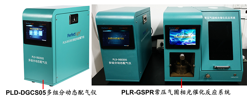
Figure 1. PLD-DGCS05 Multi-Component Dynamic Gas Mixing System used in conjunction with PLR-GSPR Atmospheric Gas-Solid Phase Photocatalytic Reaction System at a customer site
Using the PLD-DGCS05 Multi-Component Dynamic Gas Mixing System, you can obtain stable flow rates of a certain concentration and certain types of gases, uniformly mixed gases, meeting the requirements of gas-solid phase reaction experiments under complex gas conditions.
1. Technical Parameters of the PLD-DGCS05 Multi-Component Dynamic Gas Mixing System:
1. Operating Pressure: Input gauge pressure is 0.21~0.66 MPa, output gauge pressure is 0.1~0.55 MPa, input pressure-output pressure 0.1 MPa;
2. Pressure Resistance: 0.7 MPa;
3. Mass Flow Controller Accuracy: ±1%F.S;
4. Mass Flow Controller Control Range: 4%~100% F.S;
5. Mass Flow Controller Range: Single channel selectable, range 15 mL/min~10 L/min;
6. Response Time: ≤2 s;
7. Number of Output Gases: Two channels, can independently select outlet 1 or outlet 2, or simultaneously select outlet 1 and outlet 2;
8. Preset Gases: Background gases - Air, N₂, Ar; Standard gases - CH₄, CO, VOCs, CH₂O.
2. Installation and Use of the PLD-DGCS05 Multi-Component Dynamic Gas Mixing System
1. Connect Inlet and Outlet Gas Lines
For inlet gas, routes 1 to 8 can be selected as needed, and each gas should be connected to the corresponding standard gas cylinder;
For outlet gas, routes 1 and 2 can be selected as needed, with the other end connected to the reaction device, as shown in Figure 2 (a), connecting the inlet and outlet joints.
Pressure-resistant hoses are used for gas connection. After installing the pressure-resistant hose, nuts, flexible rings, and waist drums should be fitted onto the pressure-resistant hose in the order shown in Figure 2 (b).
Note: Ensure that the gas source pressure at the inlet is higher than 0.1 MPa but lower than 0.6 MPa.
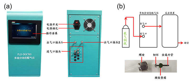
Figure 2. (a) Front and rear panel diagrams of the PLD-DGCS05 Multi-Component Dynamic Gas Mixing System, (b) Schematic diagram of pipe connection
2. Self-Check
Connect the power supply to the PLD-DGCS05 Multi-Component Dynamic Gas Mixing System, turn on the power switch, and click anywhere on the startup interface for self-check. After passing the self-check, it will automatically enter the main page as shown in Figure 3.

Figure 3. PLD-DGCS05 Multi-Component Dynamic Gas Mixing System self-check process diagram
3. Setting Gas Parameters
Click on the Gas Parameter Entry option on the main page to enter the Gas Parameter Setting interface as shown in Figure 4.

Figure 4. PLD-DGCS05 Multi-Component Dynamic Gas Mixing System gas parameter setting
Gas Number: The gas number corresponds to the inlet, and cannot be changed; for example, G1 corresponds to inlet 1, and so on;
Background Gas: The gas after diluting the target gas, can be set to N₂, Ar, or Air as shown in Figure 5. If the target gas is pure gas, you can choose any background gas;
Target Gas: Click to set the target gas, which can be set to various gas types such as CO, NO, CH₂O, and others as shown in Figure 5.
Concentration Setting: Concentration of the target gas, can be set by clicking, and input the value directly using the numeric keypad as shown in Figure 5.
Unit Selection: Unit of concentration of the target gas, can be set by clicking, and can be set to ppm or C% as shown in Figure 5.
If the target gas is pure gas, after selecting any background gas, set the concentration to 100 and select C% as the unit.
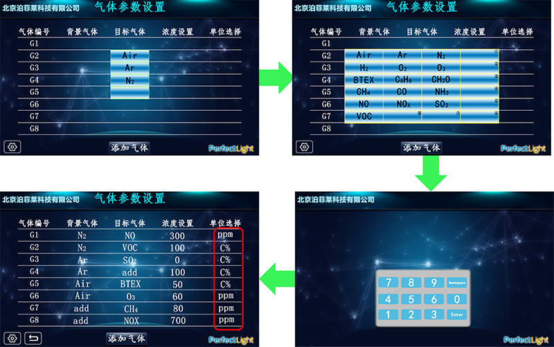
Figure 5. PLD-DGCS05 Multi-Component Dynamic Gas Mixing System gas parameter setting page
4. System Configuration
After completing the target gas settings, you can enter the working mode to start the experiment. By controlling the flow rate of each gas route, you can control the total gas flow rate and gas ratio at the outlet, suitable for experiments where flow rate and gas ratio do not change during gas flow.
Click the button to enter the Flow Rate Setting page. Click the flow rate setting dialog for each gas route, and input the gas flow rate value via the numeric keypad according to the experimental requirements.
Click the Outlet Switch button and select outlet 1 or 2 according to the gas route connection method, as shown in Figure 6. After setting, click the button again to return to the operation page.
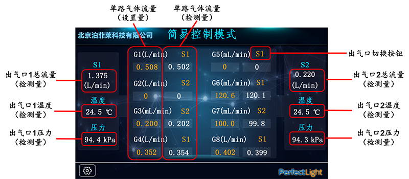
Figure 6. PLD-DGCS05 Multi-Component Dynamic Gas Mixing System Simple Control Mode Setting Page
5. Running the System
Press and hold  button for 5 seconds to start the system. The system will adjust the flow rates to the set values. At this time, the actual flow rate, temperature, and pressure values at the outlets will appear in the dialog boxes on both sides of the Simple Control Mode Setting page.
6. Stopping the System
Press and hold  button for 5 seconds to stop the system, and all gas flows will return to zero.
Three. Precautions for the PLD-DGCS05 Multi-Component Dynamic Gas Mixing System
1. If toxic or harmful gases are used, strict personal protective measures must be taken, and tail gas treatment devices must be added. Carefully check the airtightness of all interfaces, and use an inert gas to purge all gas paths after gas mixing;
2. The gas input gauge pressure is 0.21~0.66 MPa;
3. The PLD-DGCS05 Multi-Component Dynamic Gas Mixing System can support up to 8 gas channels at most, and you can select the specific number of gas channels according to your experimental requirements;
4. A pressure reducing valve must be installed in front of the inlet of each gas route;
5. When not in use for an extended period, be sure to disconnect all gas sources;
6. All flow rates inside the PLD-DGCS05 Multi-Component Dynamic Gas Mixing System refer to flow rates under standard conditions of 0°C and 101.325 kPa unless otherwise specified.
Four. Adding Gases to the PLD-DGCS05 Multi-Component Dynamic Gas Mixing System
If there is no background gas or target gas needed for the experiment in the Target Gas Settings page, you need to add gases.
Click the Add Gas button on the gas settings page to enter the gas adding settings page as shown in Figure 8. You can add one background gas and eight target gases. Click the blank box in the Gas Type dialog box to add gases.
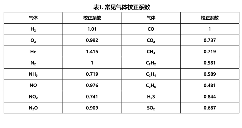
After clicking the blank box in the Gas Type dialog box, a full keyboard will appear as shown in Figure 7. Enter the molecular formula of the gas to be added, and enter the correction factor in the dialog box. For commonly used gas correction factors, refer to Table 1.
After entering, click  , and then click
  to return to the gas parameter setting page.
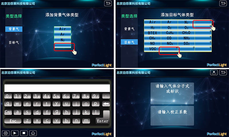
Figure 7. PLD-DGCS05 Multi-Component Dynamic Gas Mixing System Gas Adding Settings Page
