The CHF-XM Series Light Sources feature a modular design, allowing for parallel light output to achieve a more uniform light spot. They are suitable for applications such as photocatalytic quantum efficiency testing, photoelectrochemical testing, and solar cell testing.
The CHF-XM Series Light Sources are divided into two categories: xenon lamp light sources and mercury lamp light sources:
- The xenon lamp light source category includes the CHF-XM150 xenon lamp light source and the CHF-XM500 xenon lamp light source;
- The mercury lamp light source category includes the CHF-XM250M mercury lamp light source and the CHF-XM500M mercury lamp light source.
In this document, both xenon and mercury lamp light sources are referred to as bulbs.
Section 1: Initial Installation of CHF-XM Series Light Sources
1. Upon receiving the CHF-XM Series Light Sources, check the external packaging for any damage. If there is extensive damage, refuse to accept the shipment, and request the courier company to handle it properly. Contact Perfectlight Technology customer service as well.
2. Unpack the lightbox, power supply box, and related components as listed in the packing list inside the product packaging, as shown in Figure 1.
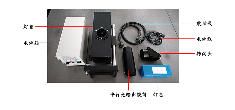
Figure 1. CHF-XM Series Light Sources Unboxing Photo
3. Place the power supply box and lightbox of the CHF-XM Series Light Sources on a stable tabletop. Ensure that the power switch is in the "OFF" position, and connect the aviation plug cable and power cable as shown in Figure 2.
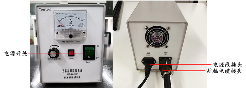
Figure 2. CHF-XM Series Light Sources Power Cable Connection Diagram
4. Bulb Installation:
Prepare a cross-head screwdriver before installation. ① Unscrew the six fixing screws on the rear cover of the lightbox, as shown in Figure 3 (a), and remove the rear cover of the lightbox, ensuring that the inner spherical reflector is placed as shown in Figure 3 (b).
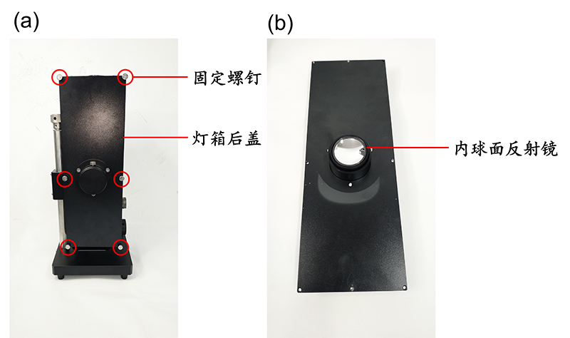
Figure 3. CHF-XM Series Light Sources Bulb Installation Diagram (Part 1)
② Remove the bulb from the packaging and, as shown in Figure 4, identify the bulb's anode and cathode;
③ Unscrew the securing nuts 1 and 2 as shown in Figure 4 (b);
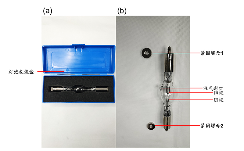
Figure 4. CHF-XM Series Light Sources Bulb Installation Diagram (Part 2)
④ Loosen the fixing screws on the upper and lower heat sinks at the positions shown in Figure 5 and place the bulb inside the heat shield. For xenon lamps, ensure the cathode is at the bottom and the anode is at the top. For mercury lamps, ensure the cathode is at the top and the anode is at the bottom. Note: For both xenon and mercury lamps, the gas-sealed end should be facing upward;
⑤ Tighten securing nut 1 on the upper heat sink and securing nut 2 on the lower heat sink by hand. Then, separately tighten the fixing screws on the upper and lower heat sinks using a cross-head screwdriver;
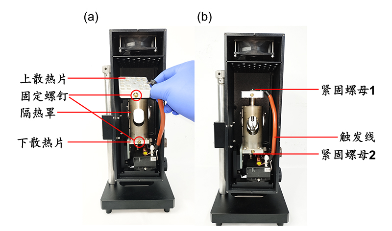
Figure 5. CHF-XM Series Light Sources Bulb Installation Diagram (Part 3)
⑥ Use the securing screws on the reflector tube, as shown in Figure 6, to confirm that the rear cover of the lightbox is facing upward. The correct installation direction is when the securing screws on the reflector tube are located at the top. Otherwise, it may affect parallel light output. After installing the rear cover of the lightbox, tighten the six fixing screws;
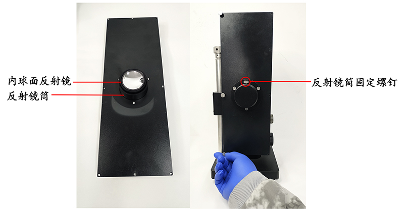
Figure 6. CHF-XM Series Light Sources Power Supply Box Installation Bulb Installation Diagram (Part 4)
⑦ Loosen the fixing screw 1 as shown in Figure 7, insert the parallel light output tube into the lightbox, and then tighten it. Next, loosen fixing screw 3, insert the turning head into the parallel light output tube, and then tighten it;
⑧ Once you've connected the aviation plug cable and power cable, the initial installation of the CHF-XM Series Light Sources is complete.
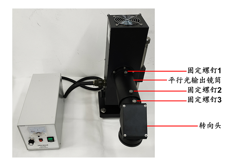
Figure 7. CHF-XM Series Light Sources Bulb Installation Diagram (Part 5)
Section 2: How to Use CHF-XM Series Light Sources
1. After confirming that all power cables are correctly connected, turn the power switch to the "ON" position. After a 30-second warm-up, press the trigger button to light up the bulb. Adjust the current adjustment knob on the front panel of the power supply box. The current value displayed on the ammeter is the current in use, with a current usage range of 13 to 21 A, as shown in Figure 8.
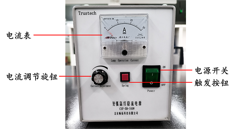
Figure 8. Front Panel of the Power Supply Box
2. Adjusting the Parallel Light Output of CHF-XM Series Light Sources:
① Adjust the direction of the turning head to be vertical downward, remove the lens cover from the top of the turning head, and place it directly below the turning head, as shown in Figure 9. Avoid directing the light source directly onto the experimental surface.
② Loosen fixing screw 3, slightly rotate the turning head left and right until the light spot, as shown in Figure 9, covers the lens cover. Then tighten fixing screw 3;
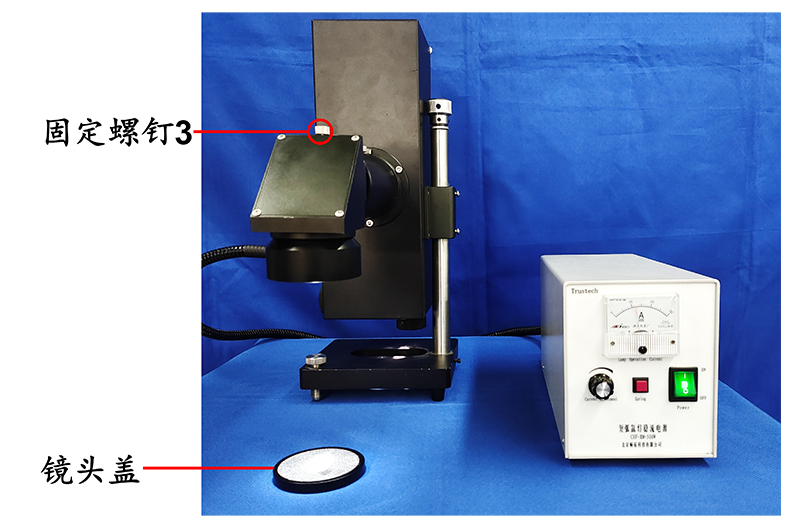
Figure 9. CHF-XM Series Light Sources Adjusting Parallel Light Diagram (Part 1)
③ Use the vertical adjustment cord knob to place the bright spot in the center of the light spot vertically and use the horizontal adjustment cord knob to place the bright spot in the center of the light spot horizontally, as shown in Figure 10.
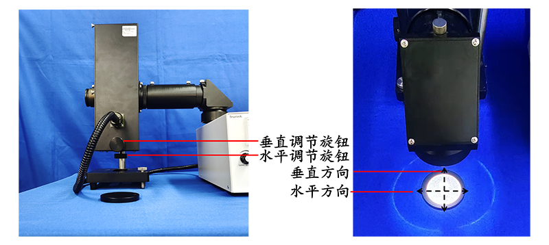
Figure 10. CHF-XM Series Light Sources Adjusting Parallel Light Diagram (Part 2)
④ Loosen the fixing screw of the reflector tube at the back of the lightbox, pull the reflector tube until the bright spot at the center of the light spot spreads out into a parallel light beam, as shown in Figure 11, then tighten the fixing screw of the reflector tube;
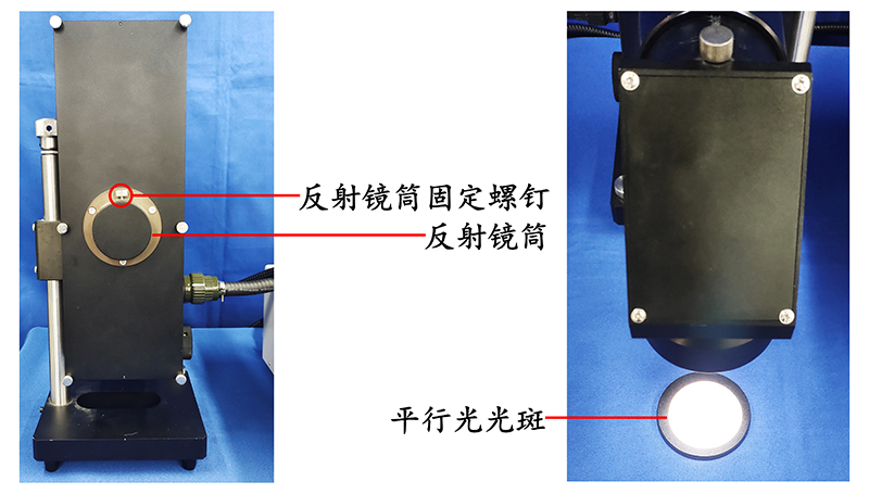
Figure 11. CHF-XM Series Light Sources Adjusting Parallel Light Diagram (Part 3)
⑤ Loosen fixing screw 2 as shown in Figure 12, adjust the parallel light output tube to change the size of the parallel light spot. Pushing the parallel light output tube inward increases the size of the parallel light spot, pulling it outward reduces the size. Once you've determined the desired size for your experiment, tighten fixing screw 2.
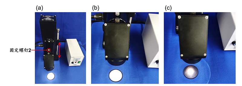
Figure 12. CHF-XM Series Light Sources Adjusting Parallel Light Diagram (Part 4)
3. Turning Off CHF-XM Series Light Sources:
After finishing your experiment, turn the power switch to the "OFF" position, and the light source will automatically turn off.
When not in use for an extended period, store the CHF-XM Series Light Sources in a cool, dry place.